

ABSTRACT
Efforts to apply augmented reality (AR) technology in the medical field include the introduction of AR techniques into dental practice. The present report introduces a simple method of applying AR during an inferior alveolar nerve block, a procedure commonly performed in dental clinics.
Keywords: Augmented Reality; Dentistry; Inferior Alveolar Nerve; Nerve Block.
INTRODUCTION
Augmented reality (AR) technology applies virtual information, such as three-dimensional (3D) images, to the real environment in an attempt to acquire more information than can be obtained from real situations. Efforts have been made to apply augmented reality (AR) technology in the medical field [1]. AR techniques have been introduced to the fields of oral and maxillofacial surgery and dentistry, but are not yet widely used [2,3]. In fact, the application of AR techniques in dental procedures is considered impractical due to the technical difficulties with its use.
The development of cone beam computed tomography (CBCT) has led to an increased use of CT in the oral and maxillofacial fields [4]. Software that reconstructs CT images into 3D images has also become widely used. Even without expensive 3D simulation software, information regarding 3D reconstruction of the jaw can easily be obtained using free or open source 3D simulation software.
Inferior alveolar nerve block anesthesia is a necessary and fundamental local dental anesthetic procedure. Although anesthetic failures can occur with inferior alveolar nerve block anesthesia for reasons such as poor anesthetic technique and anatomical variation, 3D anatomical positioning of the mandibular foramen is important for the procedure. The three-dimensional position of the mandibular foramen relative to the anatomical structures of the oral mucosa is helpful for the block procedure because it can be used as a reference for anesthetic injection. The present report introduces a simple method for applying AR during an inferior alveolar nerve block procedure, which is commonly performed in dental clinics.
TECHNICAL NOTE
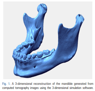
Here we describe the generation of an AR using CT images of a patient’s mandible to create a 3D image of the mandible, combined with real images of the oral cavity. We extracted digital imaging and communications in medicine (DICOM) files from the available mandibular CT data, including information obtained during the examination of a maxillofacial deformity or before the extraction of a mandibular third molar. The DICOM files were imported into 3D reconstruction software (i.e. Simplant [Materialise Dental, Leuven, Belgium], Mimics [Materialise, Leuven, Belgium], InVivoDental [Anatomage, San Jose, CA, USA], OnDemand3D [CyberMed Inc., Seoul, Korea], OsiriX Imaging Software [Pixmeo, Geneva, Switzerland], 3DSlicer open source software [http://www.slicer.org]) to produce 3D images of the mandible. The software must enable the reconstructed 3D mandibular images to be positioned, rotated, enlarged, and reduced. 3D movement of the mandibular image are possible with all the previously mentioned software. Using any of these software programs, DICOM data for the CT were converted to stereolithography (STL) file formats. The following is an example of a DICOM to STL conversion. The DICOM files were opened in Mimics software (Materialise, Leuven, Belgium). DICOM CT data were converted to STL files with the following settings: threshold values to construct 3D images of the CT data were set to 226–3071 Hounsfield unit (these were the threshold values previously set for bones in the Mimics program). The 3D structure quality was set to the optimal 3D calculation in the Mimics program. The areas of the temporomandibular joint and teeth were separated from the craniomaxillary area for only the mandibular segmentation in the case of the facial CT. If using the STL data of the mandible, computer-aided design-related software also are able to reconstruct 3D mandibular images for positioning, rotation, enlargement, and reduction. In the current method, Rapidform Explorer, which is free software (INUS Technology, Seoul, Korea) was used to manipulate the mandible using 3D movement for AR. Another software program (i.e. transparency_utility, Actual Transparent Window [Actual Tools, Vancouver, Canada]) that can adjust window transparency must also be installed on the same computer. To reduce the time required for the actual procedure, the steps for the preparation of the 3D mandible reconstruction should be completed prior to preparing the patient for surgery (Fig. 1).
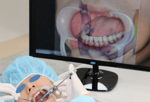
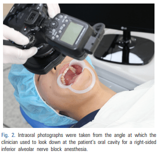
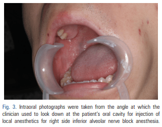
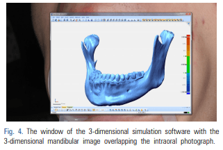
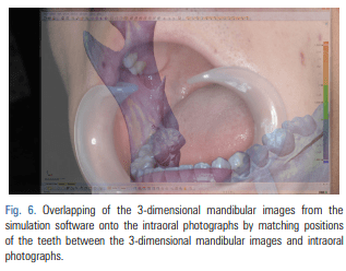
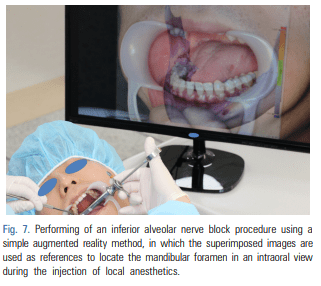
For patients requiring an inferior alveolar nerve block for extraction of the third molar or other dental treatment, a digital camera was used to take intraoral photographs to obtain the images of the actual oral cavity immediately before administering inferior alveolar nerve block anesthesia. In such cases, the patient was instructed to open his or her mouth in the same manner as during an inferior alveolar nerve block. The intraoral photographs were taken from an angle similar to the one the clinician would use to look down at the patient’s oral cavity during the injection of a local anesthetic (Fig. 2). These photographs were uploaded to a computer to be overlapped with the 3D mandibular images (Fig. 3). Next, the 3D mandibular images displayed on the software were arbitrarily overlapped with the intraoral photographs on the computer screen (Fig. 4). Another software program was used to adjust the window transparency of the software displaying the 3D images of the mandible, until the intraoral photographs were visible in the background (Fig. 5). Finally, the 3D mandibular images were enlarged, reduced, rotated, and positioned as needed so that the positions of the teeth in the 3D images matched those in the intraoral photographs (Fig. 6). Using this simple AR method, the superimposed images were referenced in order to locate the mandibular foramen on the intraoral view during local anesthetic injection, while performing an established procedure for inferior alveolar nerve block (Fig. 7).

DISCUSSION
In this report, we introduced a simple method for applying AR techniques to dental practice. The described AR techniques combine real images of the oral cavity with 3D mandible images generated from the CT images of a patient’s mandible. Such methods are employed in dental clinics for detection of dentofacial deformities and observation of the inferior alveolar nerve canal of the jaw [2,5].
Since free/open source software are easy to access, expensive 3D simulation software is unnecessary for the current AR method. The 3D reconstruction software allows the user to simply enlarge, reduce, and rotate 3D jaw images using only a keyboard and a mouse. Software enabling window transparency adjustment is also highly accessible and easy to use.
In the method described here, tooth areas within the CT images of the jaw were replaced using optical scanning data for these teeth and subsequently, these data were merged and reconstructed into 3D images. Next, the generated 3D mandibular images were superimposed onto real oral photographs by aligning the position of each tooth to create an augmented reality. It may not always be necessary to obtain CT images with the tooth images replaced using optical scan data, particularly when the augmentation between 3D mandibular images and oral photography is performed for the purpose of using simple AR to gain supplementary information for an inferior alveolar nerve block. However, this procedure may be required to generate sufficiently accurate 3D images of the teeth of patients with an orthodontic bracket or multiple prosthodontics. In such cases, the tooth area from the CT images should be interpreted using a digital dental cast or optical scanning of the teeth [6].
The inferior alveolar nerve block is a commonly performed procedure in the field of dentistry. It requires accurate identification of the anatomical location of the mandibular foramen, which varies among patients [7]. We are now capable of obtaining greater information about the mandibular foramen through 3D reconstruction of available CT images [8]. However, the 3D information provided by this method is limited if the technique is not accompanied by direct observation of the oral cavity. We attempted to overcome this limitation with the method described here. There is currently no defined protocol for the use of AR techniques or for the superimposition of clinical and 3D images [1,9]. In general, AR techniques involve the use of devices to monitor patient movement and reflecting these movements in an AR [10]. However, it is not yet clear how tracking devices should be used for patient movement or where on the body they must be attached [1,3]. There also remains a need to assess the accuracy of the positional information provided by these devices. Overall, the advantages of AR techniques are accompanied by multiple limitations, including the difficulty of their technical application and their limited accuracy. However, we believe that AR techniques should be used wherever they can provide useful information and can be easily used in a clinical settings. For this reason, we have introduced the simple AR techniques described herein. Future studies are needed to investigate the accuracy of the superimposition method.
In our technique described here, we attempted to create an AR on a monitor. Clinicians can view clinical images on a monitor, through transparent glass, or on a headmounted display [5], with the monitor being the simplest technique. In this study, the inferior alveolar nerve block was performed quickly and with the aim of obtaining supplementary information regarding the shape and location of the mandibular foramen. In this situation and with the patient remaining stationary, it was appropriate to view the clinical images using a monitor.
Three-dimensional anatomical positioning of the mandibular foramen is important to the procedure for an inferior alveolar nerve block anesthesia. The position of the mandibular foramen should be found threedimensionally relative to the oral anatomical structures. Using the AR technique, the anatomical structures in the oral cavity that are selected as anatomical references should be easy and convenient to use regardless of the skill of the operator and the error in the positioning of the mandibular foramen should be small. Using the augmented bone structures in the oral cavity as references to optimize the position of the mandibular foramen may increase the efficiency of the procedure for an inferior alveolar nerve block. Thanks to the recent commercialization of computed tomography (CT) and the development of computer software including commercial and open software, studies of the anatomical structures of the human body have progressed. Our technique required a few more minutes to perform when compared to the conventional method for obtaining an augmented image prior to performing an inferior alveolar nerve block. Although additional time was required for AR, the current AR technique provided related informations for bony structures in the oral cavity that can be referred to during anesthetic injections in order to easily and accurately locate the position of the mandibular foramen for an inferior alveolar nerve block. These attempts at applying AR techniques to dental treatment may lead to the development of clinically applicable AR techniques. They can also be widely used for education dentistry and in the oral and maxillofacial fields.
Our technique only required a few minutes to obtain 3D CT images of the mandible, extract DICOM data, and import the data to the software prior to performing an inferior alveolar nerve block. In the clinical setting, it takes only a few seconds to transfer intraoral images from a digital camera or other device to the computer. Similarly, it required only a few seconds to adjust the window transparency of the 3D simulation software on the monitor and a minute to position, rotate, and adjust the magnification scale of the 3D images of the mandible to match the tooth area between an oral photograph and 3D mandibular image. Simple processes for applying AR techniques, as described here, may enable the routine clinical application of AR in dental practice.
Simple AR techniques, such as those described in this report, may be performed as a supplementary step in the detection of impacted teeth and jaw cysts that are difficult to observe in clinical practice. These simple attempts at applying AR techniques to medical treatment may lead to the development of clinically applicable AR techniques that can be used widely in the medical field, including dentistry and the oral and maxillofacial fields.
CONFLICTS OF INTEREST: The authors have no conflicts of interest to declare.
Source
https://pubmed.ncbi.nlm.nih.gov/28879340/
References
- Suenaga H, Tran HH, Liao H, Masamune K, Dohi T, Hoshi K, et al. Vision-based markerless registration using stereo vision and an augmented reality surgical navigation system: a pilot study. BMC Med Imaging 2015; 15: 51.
- Zhu M, Liu F, Chai G, Pan JJ, Jiang T, Lin L, et al. A novel augmented reality system for displaying inferior alveolar nerve bundles in maxillofacial surgery. Sci Rep 2017; 7: 42365.
- Kobayashi E, Sakuma I, Wang J, Suenaga H, Hoshi K, Yang L, et al. Augmented reality navigation with automatic marker-free image registration using 3-D image overlay for dental surgery. Int J Med Robot 2014; 61: 1295-304.
- Hernandez Y, Tarazona B, Zamora N, Cibrian R, Gandia J, Paredes V. Comparative study of reproducibility and accuracy in measuring mesiodistal tooth sizes using three different methods: 2D digital, 3D CBCT, and 3D CBCT segmented. Oral Radiol 2015; 31: 165-72.
- Badiali G, Ferrari V, Cutolo F, Freschi C, Caramella D, Bianchi A, et al. Augmented reality as an aid in maxillofacial surgery: validation of a wearable system allowing maxillary repositioning. J Craniomaxillofac Surg 2014 ;42: 1970-6.
- Kang SH, Lee JW, Lim SH, Kim YH, Kim MK. Dental image replacement on cone beam computed tomography with three-dimensional optical scanning of a dental cast, occlusal bite, or bite tray impression. Int J Oral Maxillofac Surg 2014; 43: 1293-301.
- You TM, Kim KD, Huh J, Woo EJ, Park W. The influence of mandibular skeletal characteristics on inferior alveolar nerve block anesthesia. J Dent Anesth Pain Med 2015; 15: 113-9.
- Kang SH, Byun IY, Kim JH, Park HK, Kim MK. Three-dimensional anatomic analysis of mandibular foramen with mandibular anatomic landmarks for inferior alveolar nerve block anesthesia. Oral Surg Oral Med Oral Pathol Oral Radiol 2013; 115: e17-23.
- Wang J, Suenaga H, Liao H, Hoshi K, Yang L, Kobayashi E, et al. Real-time computer-generated integral imaging and 3D image calibration for augmented reality surgical navigation. Comput Med Imaging Graph 2015; 40: 147-59.
- Suenaga H, Hoang Tran H, Liao H, Masamune K, Dohi T, Hoshi K, et al. Real-time in situ three-dimensional integral videography and surgical navigation using augmented reality: a pilot study. Int J Oral Sci 2013; 5: 98-102.